The circuitry in the 22AV5530 is quite complex and provides switching functions not included in the VCRs. It provides interface not only to audio and composite video input and output signals but serial control data intended for interface to Philips camera units.
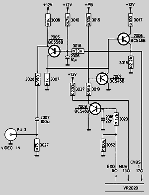
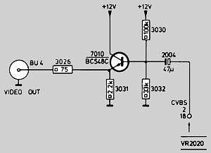
If you wish to get External Video in to a V2020/1/2/3 then the signal needs to be amplified and fed to Pin 17. Similarly Video Output from Pin 18 needs to be buffered before it can drive a 75 ohm line.
Simple interface Circuits

Video in circuit

Video out circuit

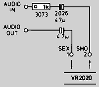
Audio in/out circuit
The 20-pin AV connector


Pin descriptions for the AV connector on the rear of the V2020/1/2/3 VCRs.
1
External Audio Input.
2
Audio Output. Internal feed to UHF Modulator.
3
+12Vd.c. Output.
4
Test Point for Bias adjustment
5
Camera Remote Out
6
External ON (XON): Goes High when channel "00" is selected.
7
Remote in. (Data via Camera)
8
Voltage Actuator Added.
9
Head to Frame Added Pulse.
10
Ground for Head Frame Added.
11
Muting: Low is no signal applied.
12
NOT REC: Goes low in Record mode,
13
Mute All: Goes low when External Video In is selected.
14
Mute Sound: Goes Low when External Audio In is selected.
15
Playback envelope track sensing. (Envelope Curve)
16
Ground for Pin 15.
17
External Video Input.
18
External Video Output.
19
NOT PB. Goes low in Playback mode.
20
Ground for Pin 1.
