
Technical
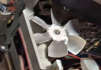
Cooling fan
|
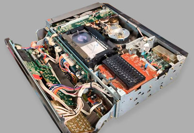
Unlike later Sanyo machine, this is a constant lace machine with the tape always in contact with the head drum.
It uses several double-sided PCBs and is well laid out and relatively tidy under the covers.
Cooling fanHeat issues appear to have been a thing with Sanyo fitting a small metal-bladed cooling fan which runs during playback, record and still modes and can be quite noisy.VideosSome videos showing this model being worked on and repaired:
|
Quick fault guide
Please click on the button if you are able to contribute a solution to this list or would like to add to, or update PALsite's information on this model. Please note, questions will be removed.If you have a question about this model, please raise it on the chatpage.
| Fault | Solution |
|---|---|
| Loss of head drum speed lock, unstable picture | Adjust VR404 (drum free run speed) on the servo board until you get a perfect picture. Replacing the capacitors is recommended. |
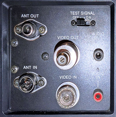
| Garbled test signal pattern | Connect the unit to an analog TV via the RF output, set the test signal switch to ON and adjust VR124 (test signal oscillator frequency) on the W1 board until the pattern is stable. |
| Rewind function causes the tape to advance forward, REW LED indicator is lit up | The rewind solenoid failed to operate because fusible resistor R977 (2.7Ω) in system control board W4 was open-circuit. This can also cause intermittent lacing. |
| Keeps stopping in playback and aborts eject | If the deck keeps stopping after pressing play and when eject is pressed it laces back up half through unlacing (hold down eject to fully eject the cassette), check the opto-coupler under the take up reel. Even if you can see the red LED, the pickup may well have become ‘lazy’. Measuring the voltage change on the output of the pickup whilst breaking the light to it should see around 13v. If it’s only a volt or two then this is defective. |
| Wavy video, unstable tracking or audio flutter | This can be caused by aging electrolytic capacitors in the servo and control boards. Recap affected boards, especially around the capstan motor and servo ICs. Check for dry joints near the head drum control. |
| Clock malfunction | Probably faulty capacitors or ICs on the clock PCB. Best to replace electrolytics on the clock board. If ICs are socketed, reseat or replace, also check for corrosion around the battery backup circuit. |
| No video output, just blank screen | Possible failed video output transistor near the AV out. |